Robotic Camera Arm

Robotic Camera Arm

Team Member

ROLE

Sept - Dec 2025

TIMELINE

Engineering Design Documentation Solidworks

SKILLS

COLLABORATORS

Arian Zargar Isaac Lavan Max Cui

SKILLS

Engineering Design Documentation Solidworks

TIMELINE

Sept - Dec 2025

ROLE

Team Member

COLLABORATORS

Arian Zargar Isaac Lavan Max Cui


OVERVIEW

As part of our 2nd year Mechanical Engineering Design course (MIE243), this project originated from an existing gap in the market: the lack of a low-cost, long-range robotic camera arm capable of producing professional cinematographic shots. The objective of the project was to create a robot that allows users to mount a camera and produce complex movements with precision. Following standard engineering design procedures, I produced design specifications and a functional SolidWorks model of the Robotic Camera Arm.


OVERVIEW

As part of our 2nd year Mechanical Engineering Design course (MIE243), this project originated from an existing gap in the market: the lack of a low-cost, long-range robotic camera arm capable of producing professional cinematographic shots. The objective of the project was to create a robot that allows users to mount a camera and produce complex movements with precision. Following standard engineering design procedures, I produced design specifications and a functional SolidWorks model of the Robotic Camera Arm.


Part 1 / Engineering Specifications

The problem was throughly analyzed and broken down into the following engineering specifications:

  • Manipulating the camera in at least 4 DoF, with at least 1 translational, 1 rotational.

  • Supporting and manipulating a 1.5 kg payload.

  • Reaching 0.75 m when fully-extended.

  • Achieving positional repeatability error of no more than ±1 cm.

  • Attaching the camera using standard mounting mechanisms.

  • Must cater to intended users’ budget and not exceed $4000 USD.

  • Must be safe for operation in proximity to multiple human users.


Part 2 / Developing Candidate Designs
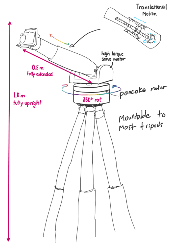


#1/ Telescopic Cantilever Arm
This is the minimum-required design addressing the most of the core engineering specifications, while focusing on simplicity.


Pros: cost-effective, supports 2kg camera load

Cons: 3 DOFs, increased backlash w/ cantilever


#2/ Continuum Robotic Arm

This design, inspired by the dexterity of continuum robotics, exceeds required benchmarks and can manipulate the camera in infinite DoFs.


Pros: infinite DOFs, low backlash/vibration,

Cons: end effector cannot support large load


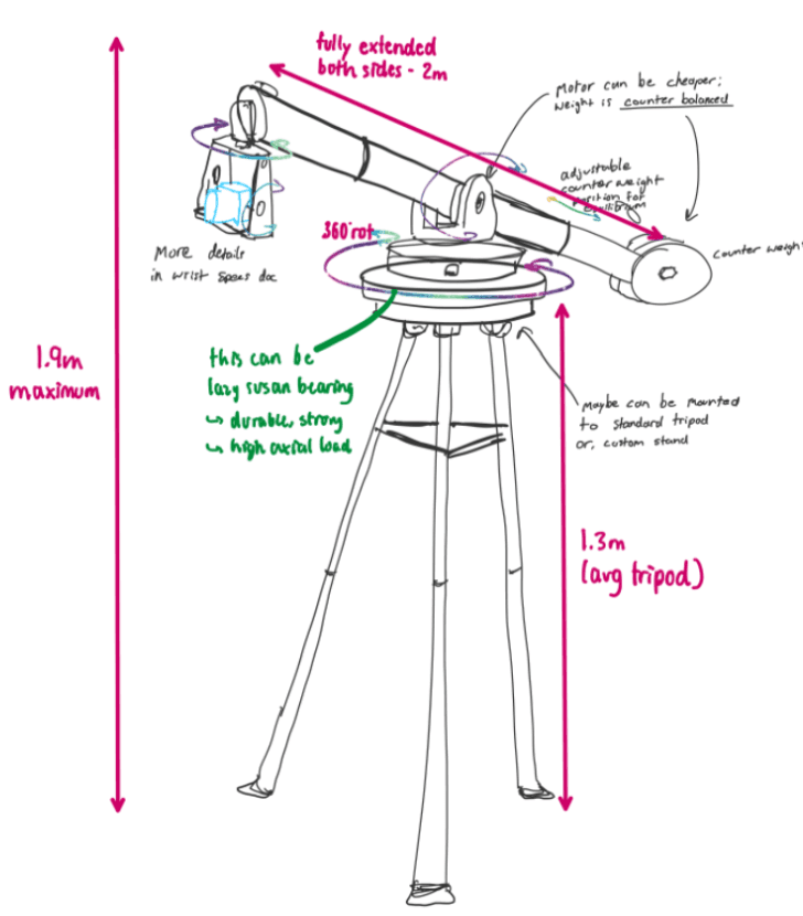
#3/ Counterweighted Arm with Rotating Head

This design incorporates the high performing mechanisms from previous designs. To reduce stress at the pivot point, the arm mounts a camera on one end and a counterweight on the other.


Pros: cost-effective, 5 DOFs, repeatable

Cons: high centre of gravity


#1/ Telescopic Cantilever Arm
This is the minimum-required design addressing the most of the core engineering specifications, while focusing on simplicity.


Pros: cost-effective, supports 2kg camera load

Cons: 3 DOFs, increased backlash w/ cantilever


#2/ Continuum Robotic Arm

This design, inspired by the dexterity of continuum robotics, exceeds required benchmarks and can manipulate the camera in infinite DoFs.


Pros: infinite DOFs, low backlash/vibration,

Cons: end effector cannot support large load


#3/ Counterweighted Arm with Rotating Head

This design incorporates the high performing mechanisms from previous designs. To reduce stress at the pivot point, the arm mounts a camera on one end and a counterweight on the other.


Pros: cost-effective, 5 DOFs, repeatable

Cons: high centre of gravity


Part 3 / Design Selection

Upon a comparative assessment of all three candidate designs against the project’s four highest-priority specifications, Design #3/ Counterweight Arm with Rotating Head emerges as the strongest design. It demonstrates consistently high performance across all engineering specifications. 

Part 4 / CAD Drawings


Functional 3D CAD models of the selected design were created using SolidWorks.


Exploded view of Camera End Effector assembly.


Exploded view of Telescopic Arm assembly.


Full Camera Arm assembly.

Full Camera Arm assembly.

#1/ Telescopic Cantilever Arm
This is the minimum-required design addressing the most of the core engineering specifications, while focusing on simplicity.


Pros: cost-effective, supports 2kg camera load

Cons: 3 DOFs, increased backlash w/ cantilever


#2/ Continuum Robotic Arm

This design, inspired by the dexterity of continuum robotics, exceeds required benchmarks and can manipulate the camera in infinite DoFs.


Pros: infinite DOFs, low backlash/vibration,

Cons: end effector cannot support large load


#3/ Counterweighted Arm with Rotating Head

This design incorporates the high performing mechanisms from previous designs. To reduce stress at the pivot point, the arm mounts a camera on one end and a counterweight on the other.


Pros: cost-effective, 5 DOFs, repeatable

Cons: high centre of gravity